We started with a steady rest from a huge Sidney geared head 24″ x 16′ lathe being scrapped laying on it’s side in the mud. Our plans came from a 1921 publication showing and oval chuck of about 12″ major diameter capacity. It was used for making rear car window frames. Our chuck has the capacity of 48″ on the major diameter. The only other oval chucks in operation this big on the East Coast are at Old Schwamb Mills in Arlington, Mass.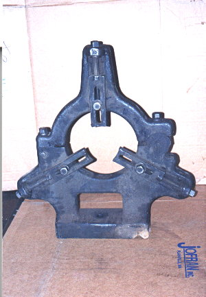 Here, we have cut out a rectangular hole in the base casting of the rest. This was done for lateral adjustment of the oval chuck assembly yeilding different shape ovals.
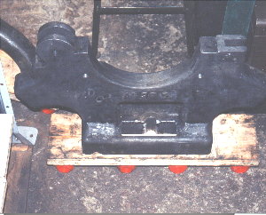 he entire steady rest was dissassembled, stripped, cleaned and oiled. This is the top casting stripped.
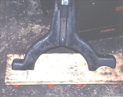 This image shows the finished modified steady rest ready for the oval chuck mechanism.
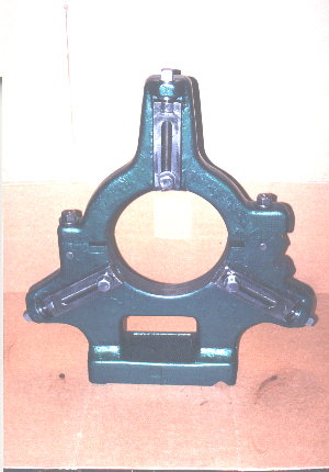 The main chuck ring was custom cast for us in cast iron. This ring was slightly over 18″ O.D. x slightly under 9″ I.D. x about 6″ wide. It weighed over 350 lbs.
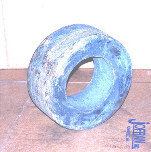 The main chuck ring is being machined on our 1911 18″ x 6′ South Bend Lathe shown elseware on this site. We were machining an angle to correspond to the “pasta pot” live center that would support this end of the casting. Due to the extreme weight and overhang of this peice we machined in light cuts and at very slow speed.
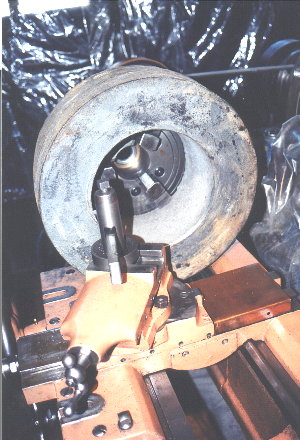 With the live center in place, we started to machine the O.D. groove that would be clamped by the steady rest jaws. Due to the casting only just clearing the lathe bed and saddle, we had to do this with a boring bar assembly.
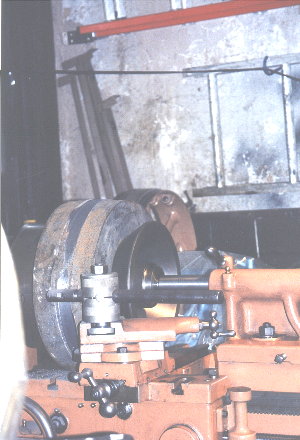 This is another view of the setup creating the main chuck ring retention groove.
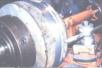 Notice the size of the huge casting in relation to the lathe. We were on the extreme limits of this machine’s capacity.
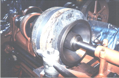 This view from the rear shows the large and rare live center in place. Tooling like this made this job possible. We like to keep the lathes as clean as possible during machining as it will less likely get clogged and jammed up with chips.
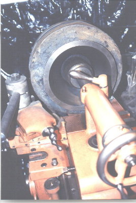 This is the bearing ring made from a custom cast for us. This cast iron ring was about 18″ O.D. x 9″ I.D. x 2″ thick.
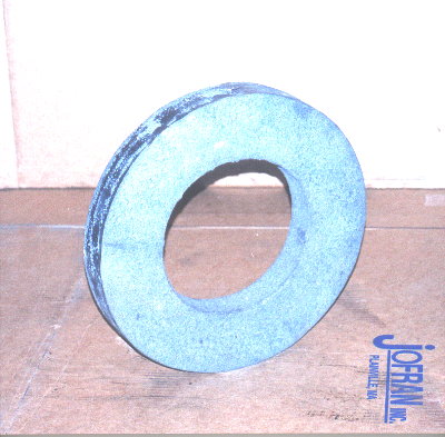 The main chuck ring is now installed and clamped in the steady rest. Shown in front is the finished bearing ring.
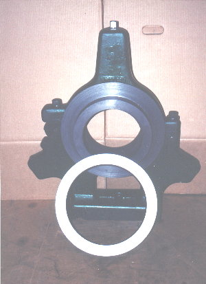 The bearing ring is shown installed on the main chuck ring.
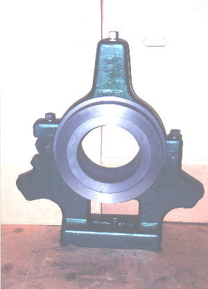 Main bearing ring slide square bars are shown here bolted and installed.
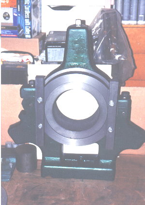 In the foreground are: (L to R) the raw materials for the oscillating plate, lathe drive shaft and the cross slide assembly.
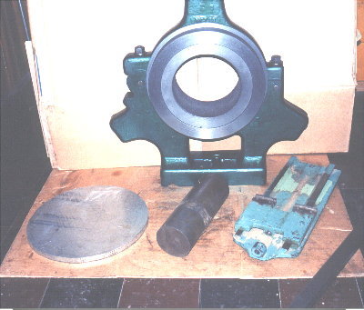 We are facing off the back of the cross slide front casting.
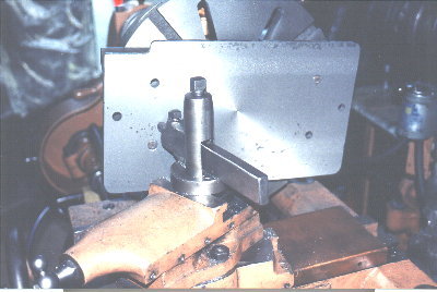 This image shows the cross slide front casting bolted to the front oscillating plate which is aluminum to save weight. The cross slide rear casting has been drilled and tapped to receive the lathe drive shaft. Note the square bar oscillating plate slides are standing above the rear cross slide casting to clear it as it slides.
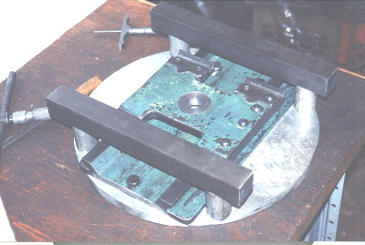 This is an end view showing the lathe end of the drive shaft. It has been drilled, bored and threaded to fit the spindle nose. Note the generous thickness given to stand the strains of use.
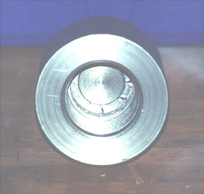 This is a 3/4 view of the lathe drive shaft.
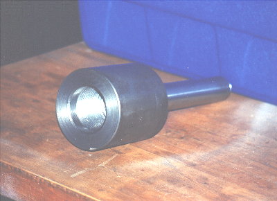 The cross slide end of the drive shaft was threaded and welded to the spindle nose hub. This tool steel shaft was also threaded to fit the rear cross slide
 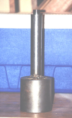 This is a side view of the finished oval chuck assembly.
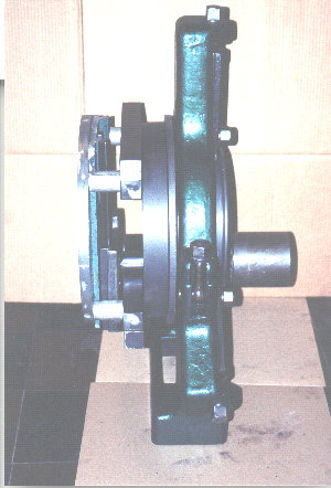 This is a 3/4 front view of the finished oval chuck assembly.
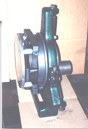 This is a 3/4 rear view of the finished oval chuck assembly.
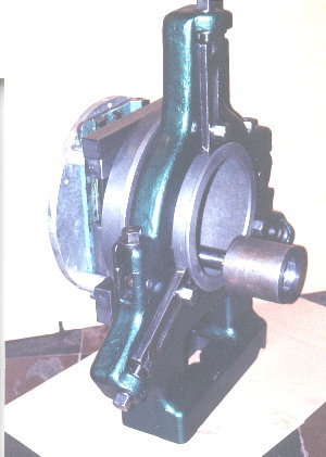 This is the rear view of the finished oval chuck assembly.
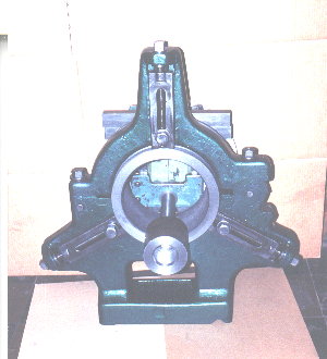 The oval chuck as shown in rear 3/4 view is installed on the lathe at French & Italian Furniture Craftsman Corp. Brooklyn, N.Y.. This lathe is a Power Turn 5′ gap 3′ sliding bed industrial woodworking lathe .
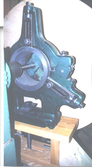 An 1 1/2″ structural laminate plywood 4′ face plate was bolted to the oscillating plate. Note the rigid wood box stand for the oval chuck and out riggers comming off it. The lathe was bolted to timber reinforcements below the floor inturn supported by concrete piers. This was done to handle the vibrational stress put upon the lathe by the chuck face plate oscillation.
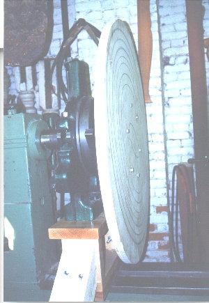 This is an overall image of the lathe with the oval chuck assembly installed. Note the different sized and shaped oval test rings generated on the face plate.
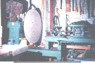 Here is a 3/4 view of the lathe and some of it’s other tooling.
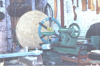 In this view the front out rigger can be seen to the lower left of the image.
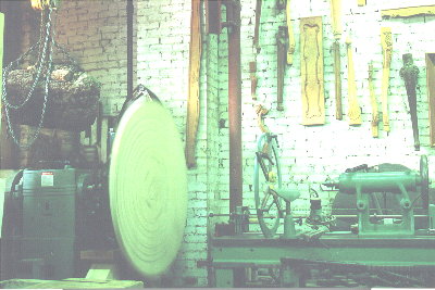
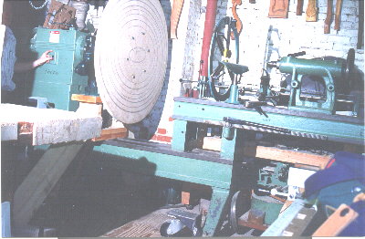 Lastly, the lathe is shown in action with the face plate oscillating at about 150 RPM.